Relational Geometry and SolidsD. Michael Shook and John S. Letcher, Jr. Copyright © 1995 AeroHydro, Inc.
AbstractWe describe Relational Geometry (RG), a logical framework for computer aided design. RG maintains a directed graph of dependencies between objects. This digraph allows an RG-based design system to capture design intent and to automatically and efficiently update a model after edits. We describe four RG based implementations: two commercial surface modelers and two solid modeler prototypes which implement RG on top of commercially available solid modeling kernels. RG is applicable to the vast majority of design projects which do not proceed linearly from beginning to end. It is especially suited to conceptual design and to creation of parametric series of models as part of a design optimization process. Extensive use of the RG surface modeler has shown that the dependency digraph can be easily understood by users and that the automatic update capability enabled by the digraph is a valuable enhancement to the modeling process. It also demonstrates that RG is effective in the design of complex, sculpted surfaces. The two RG/solid modeler prototypes demonstrate that RG's benefits can be extended to solid modeling. RG is a novel addition to the field of editable, automatically updateable modeling methods which includes dimension-driven, variational and parametric modelers. The simplicity of the RG concept provides significant benefits for both implementation and use. MotivationThe utility of many solid modeling systems has been limited by one or more of the following deficiencies:
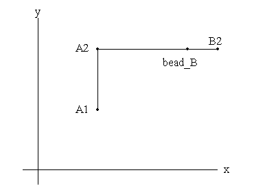
Over the past decade, much work has gone into addressing these issues. Parametric, variational and dimension-driven modelers attempt to capture design intent. [Armit, Brown, Gossard et. al., Hanratty, MacKrell, Sutherland] The use of a single representation for geometry, such as non-uniform rational B-Splines (NURBS), along with extensive libraries of routines for creating geometry in the chosen representation, has been the major thrust in attempting to deal with limitations in the variety of curve and surfaces types. [Farin, Riesenfeld]. The problem of intersection of two surfaces is inherently difficult, for several reasons. The intersection may be empty. Finding any single point of intersection requires solution of three simultaneous, usually nonlinear, equations. These equations may be a single point, a simple arc, a closed curve, a self intersecting curve, or multiple combinations of these elements. The surfaces might indeed coincide over some finite area. [Letcher] Relational GeometryRelational Geometry (RG) is a framework for geometric modeling which addresses all these issues. At the core of RG is an acyclic directed graph or digraph. The nodes of the graph are geometric objects. The arcs represent the dependency relationships between the geometric objects. A simple model provides an example. Fig. 1 display a model consisting of three points and two lines:
Fig. 1. A simple relational model consisting of three points and two lines. Listing 1 displays the RG model file which describes this model.
Listing 1. The RG model file representation for the model of Fig. 1. Each line of the model file describes an object in the model. This simple model consists of objects which are instantiation of one of three entities, AbsPoint, Line or AbsBead. RG entities and objects correspond to the "classes" and "objects" in object-oriented programming terminology. Each object description has a entity name, an object name and object data and supports.
Entity name        Object name        Object data and    Description
                                      supports
AbsPoint           A1                 2. 2. 0.           x, y and z
                                                         coordinates of
                                                         point
Line               line_A             A1 A2              Name of end
                                                         points
AbsBead            bead_B             line_B .25         Supporting curve
                                                         and t
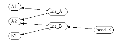
Table 1. Components of sample object descriptions. Fig. 2 show the digraph described by the model file.
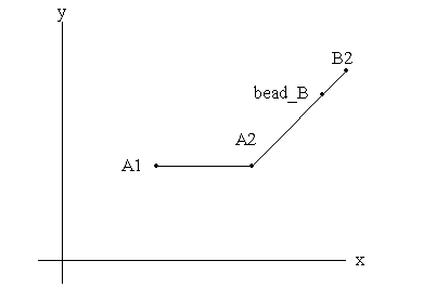
Fig. 2. The digraph representing the model of Fig. 1. When referring to the digraph, we speak in terms of supports and dependents. A1's only dependent is line_A. line_B's supports are A2 and B2. Supports and dependents can be either direct or indirect. bead_B's direct support is line_B. bead_B's indirect supports are A2 and B2. An internal representation of the digraph allows the user of an RG based interactive modeler to edit the model while maintaining the relationships. The modeler accomplishes this by using the digraph to recursively update any dependents of an object after the object is edited. Thus if the user moves point A2 to 3,2,0 all objects supported by A2 are automatically updated.
Fig. 3. The model of Fig. 1, following a change in position of point 'A2'. While the RG digraph enables a system to capture user intent and provide the powerful automatic update function, a rich collection of entities are necessary for a complete and useful modeler. The most extensive current RG implementation includes 20 point entities, 32 curve entities and 23 surface entities. These include many entities embedded in objects of higher or equal dimension:
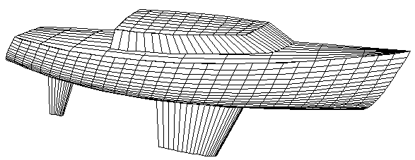
A bead object is shown in the previous examples. The essential interchangeability of these entities within each dimensionality class is facilitated by consistent parameterization: all curves are parameterized from 0 to 1; all surfaces are parameterized from 0 to 1 in both u and v. Constrained entities can be used interchangeably with other entities of the same dimensionality. Thus, in the example above, bead_B could be used as a support for a curve, the same as any other point object. ImplementationsTo date there are four RG implementations. Chronologically, they are: MultiSurf for DOSThe MultiSurf surface modeler first shipped in September 1992. Its two years of use in the interim is empirical evidence of the viability and utility of RG as the basis for an interactive geometric modeler. The value of an object in MultiSurf is a table. For surface objects this table contains a rectangular array of 3d points representing points at the intersections of the u and v isoparms of the surface. For curve objects it contains a vector of 3d points and for point objects it contains a single 3d point. This value representation leads to two evaluation modes: fast and accurate. In fast mode, when the evaluation of an object requires a position at a particular parameter value on a supporting object, that position is determined by linear interpolation in the table. In accurate mode the table is not used; the supporting object is explicitly evaluated with the parameter value. MultiSurf uses an after edit update protocol. After each edit, the value of each dependent objects is recursively updated. There are provisions to limit the update to a user specified number of levels. MultiSurf demonstrates how an RG based system can avoid difficulties associated with surface-surface intersections and trimming of surfaces along such intersections. RG provide several ways to accomplish this: 1. Two lofted surfaces will join accurately and durably along a common edge if they are of the same type, they have the same number of defining curves, and the defining curves share endpoints. 2. RG supports several surface entities that interpolate 2 or 4 boundary curves. Two such surfaces that share the same defining curve will have a durable common edge along that curve. 3. It is possible to join a surface to a second, supporting surface, not along an edge of the supporting surface but somewhere in its interior. This is done by using a snake on the supporting surface. The dependent surface is defined using a surface entity that interpolates its edges and the snake is used as one of its defining edge curves. Methods 2 and 3 involve designing the curve of intersection first and then attaching the surfaces to it. It is not surprise that this is far easier to execute than the usual intersection-trimming method. Fig. 4 demonstrates these techniques. All surface joins in this model are mathematically exact. The deck and the hull are both parametric spline surfaces which interpolate their controlling curves (MultiSurf CLoftSurf objects.) Their defining curves share endpoints along the join between the deck and hull. Each of the three sides of the cabin is a ruled surface. The top edge of each ruled surface is defined by a curve which is also used to define an edge of the top of the cabin, which is a blended surface. The bottom edge of each of these ruled surfaces is defined by a snake embedded in the deck.
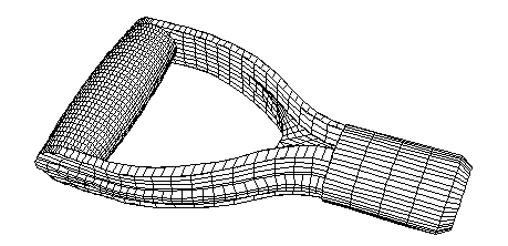
Fig 4. RG model demonstrating accurate, durable surface joins Fig 5 shows a complex model modeled with MultiSurf. In its first year MultiSurf had no intersection or projection entities and many complex models have been built without them including the models in Figs. 5 and 6. However, many users requested such entities and MultiSurf now supports intersection snakes and projection snakes.
Fig 5. Shovel handle modeled with 82 objects including 14 surfaces RG/AGThe prototype RG/AG implementation was used to explore a number of ideas and techniques including: RG implementation on top of an existing geometry library
The prototype RG/AG implementation was the first attempt to implement an RG layer on top of an existing geometry library. The obvious object oriented nature of the point/curve/surface class hierarchy (entity hierarchy in RG terminology) seemed to beg for a C++ implementation. The RG/AG implementation was strongly motivated by the Silicon Graphics Inc. (SGI) Iris Inventor display and rendering library. Inventor is an object-oriented C++ class library implemented on top of SGI's procedural Graphics Library (gl) C language bindings. Inventor objects contain member variables which describe geometry and can be arranged in a digraph with composite objects making reference to other objects. The inventor engine provides for automatic traversal of the digraph for display and rendering. In a parallel manner, RG/AG is an object-oriented C++ class library implemented on top of Applied Geometry's procedural AGLib. The RG/AG engine, implemented principally in the RGObj class, provides for automatic traversal of the digraph to reconstruct the model via calls to AGLib functions, as necessary, after edits. RG/AG is the first implementation of the on demand update protocol. In this scheme, after an object is edited, the system recursively invalidates dependent objects. Neither the edited object nor its dependent objects are reevaluated at this time. No object is reevaluated until its value is required. An objects value may be required for display or in the course of the evaluation of a dependent object. This protocol prevents some object evaluations which occur unnecessarily in with the after edit update protocol. The value of an RG/AG object is a pointer to an AGLib object (an AG_OBP). For curves and surfaces an AGLib object points to the control points, knot vectors and weights necessary for the NURBS representation of the geometry. An RG/AG object has a pointer to each of its supporting objects. Evaluation of an RG/AG object involves obtaining the value of each supporting object (which will force the evaluation of the supporting objects that are not valid) and then calling the appropriate AGLib geometry creation function. In a complete RG/AG implementation there would be an RG/AG entity for each AGLib geometry creation function. In addition, the RG/AG constrained entities would map to AGLib evaluation, projection and intersection functions. In fact, RG/AG also allows entities with table values to be mixed entities with AG_OBP values. Translation between value types is encapsulated in functions at the point/curve/surface level in the class hierarchy, and again, evaluation is on demand. The emphasis in the RG/AG implementation was building a clean, object-oriented application interface for the creation and editing of objects. A third-party set of collection classes was used (tools.h++). RG/AG relies on the serialization mechanism of tools.h++ for writing and reading model files. Although tools.h++ has provisions for both binary and ASCII serialization, the ASCII serialization does not provide an adequate human readable and editable form similar to the MultiSurf model file or the Inventor scene file.
Listing 2. C++ code to build the model of Fig. 1 in the RG/AG implementation.. Listing 2 shows the C++ code needed to build the sample model (excepting bead_B). This code points up several differences between MultiSurf and RG/AG. First, in RG/AG all numbers are objects. Second, there is no absolute point entity in RG/AG. The function of an absolute point is filled by a relative point with a null support point. Another RG/AG innovation is the object list entity. In MultiSurf, many entities include a list of supports, either because there are an indeterminate number of supports (B-spline curve, lofted surfaces, etc.) or because there are enough supports that it is convenient to use a list rather than a separate name for each support (e.g. blended surface). Having a separate object list entity means that the list editing member functions (append, insert, delete, etc.) need occur only for that entity, rather than having distinct list editing member functions for each of the entities that have support lists. With number entities and list entities, most geometric entities simply consist of a number slots which contain pointers to other entities. Get and Set are the only member functions which are required for these slots. The mechanism for maintaining referential integrity between objects is encapsulated in the RGObj class which is the parent of all number, geometry and list classes. RG/ACISThe next RG implementation was RG/ACIS, a prototype based on Spatial Technology's ACIS solid modeling kernel [Spatial Technology]. It was built on the ideas and techniques of MultiSurf and RG/AG and then it explored:
While AGLib supports building and evaluating solid models, we did not explore these capabilities in RG/AG. Rather, with our background in surface modeling, and AGLib's strength in free form surface modeling we worked with the surface modeling components of AGLib which correspond to the functionality of MultiSurf. While evaluating ACIS [Spatial Technology Inc.] we decided to implement RG/ACIS around the core of ACIS functionality exposed in the ACIS 3D Toolkit. The ACIS 3D Toolkit "is a suite of tools that provides functionality commonly needed by ACIS-based application." The ACIS 3D Toolkit presents the highest level interface to the ACIS solid modeler available from Spatial Technology. It presents two interface language options: C++ and Scheme. Because we were intending to implement an exploratory prototype, we chose the Scheme option as "the road less traveled." We used Oliver Laumann's oops.scm which is six pages of Scheme code that implement a simple, single inheritance, polymorphic object-oriented Scheme extension. This object-oriented extension enabled us to use the same structure for RG/ACIS that we had used in RG/AG. The value of an RG/ACIS geometric object is an ACIS entity. Note that in ACIS terminology an entity is similar to an RG object.
Listing 3. Scheme code to build the model of Fig. 1 in the RG/ACIS implementation.. Listing 3 displays the Scheme code to build our sample model. Like RG/AG, RG/ACIS has number entities. The rg-position:make constructor builds a number object for each of the three coordinates. RG/AG could implement a similar constructor which would have shortened the RG/AG code in Listing 2. A C++ implementation can overload a constructor or member function with different formal parameters. With oops.scm, this must be done with run-time type checking. A second difference between the RG/AG and RG/ACIS examples is that there are no object names in the RG/ACIS, while object names are an integral part of the MultiSurf implementation. They provide two important functions: object selection (as an alternative to screen picking) and object identification in the model file. It became apparent in the RG/AG implementation that the object name could be considered an object attribute similar to other object attributes such as color and layer. With the object serialization provided by collection classes object names are not needed for unique identification. Further, the kernel/husk metaphor prevalent in ACIS led us to think in terms of encapsulating object naming functionality in a object name husk.
Listing 4: Scheme code to build solid with selected blended edge from four edge entities To implement edge blending in RG/ACIS we had to create two new types of entities: list valued entities and a list reference entity. Listing 4 displays the Scheme code to build a wire body from four edges, sweep the wire body into a solid and blend selected edges of the solid. List valued objects can be used anywhere an object list is used. Thus, the last five lines of code in listing five can be replaced by(define s1 (rg-solid:blend-edges:make es 4)) This would blend all the edges rather than blending only the three selected by the rg-list-ref objects. The code in listing 4 demonstrates complications to the RG framework which did not exist in previous RG implementations. The system marks as 'deleted' most of the edges in object es created by rg-entity:edges:make when the code creates object s1 with the rg-solid:blend-edges:make constructor. This includes the edges which are the values of ed1, ed2 and ed5. The system marks these edges when it creates the new, blend faces and trims the original faces. The interpretation of the digraph is muddied by the realization that the value of objects s and s1 are in fact the same ACIS body entity. MultiSurf for WindowsThe geometry engine of MultiSurf for Windows began as a mechanical translation from Basic to C of the original MultiSurf kernel. We realized large performance gains by exploiting the large, flat address space available in 32 bit Windows. MultiSurf for Windows uses the on demand update protocol first explored in RG/AG. It may also implement a general objects list entity. Outside the kernel, the Windows user interface controls will allow exploration of many user interface options which were not practical in the original MultiSurf. MultiSurf for Windows remains a surface rather than a solid modeler. RG compared with other relational technologiesRelational Geometry can be compared with other relational technologies. Among these are: HistoriesSome interactive geometric modelers maintain a history of commands. In some of these systems it is possible to backup the model to one of these commands, change the parameters of the command and then replay some or all of the subsequent commands. While such a capability bears a superficial similarly to Relational Geometry its sequential nature doesn't capture the relationships between object that are found in the RG digraph. In addition, it cannot support selective update of only the parts of a model that are affected by an edit. Relational LanguagesAPT [APT] and XAG [Applied Geometry] are examples of relational geometric languages. APT (Automatically Programmed Tools)
Listing 5 shows a fragment of APT code to describe a circle passing through one point and centered on another. It clearly displays that APT has relational capabilities similar to RG.
Listing 5. APT code fragment. XAG (X Applied Geometry) is an Applied Geometry extension of XIG (X Interactive Geometry). XAG executes a script language of geometry commands and displays the resulting scene. Listing 6 displays XAG code to build the sample model. Like APT, is shows that XAG has relational capabilities. XAG encapsulate much of AGLib functionality as would a full RG/AG implementation.
Listing 6. XAG code to build the model of Fig. 1. In fact, the representation used in the RG model file may be considered a relational language. The difference between RG and these relational languages is that RG builds an internal representation (the dependency digraph) of the model which may be used as part of a system for interactively creating and editing geometric models. In addition, like histories, these relational languages are inherently sequential and thus cannot support selective update of only the parts of a model that are affected by an edit. Parametric and Variational SystemsMacKrell makes the following distinction between parametric and variational systems:
In comparing the two approaches he continues:
Anyone reading the CompuServe CAD forums over time would find that same idea expressed many times amidst vehement partisan exaltations and condemnations of particular systems and methods. In the parametric/variational dichotomy outlined by MacKrell RG would be considered parametric. We would distinguish RG from parametric systems in two ways. First, RG encapsulates the equations in geometric entities. Second, while the relationship between RG objects is unidirectional, those relationships are available for explicit editing by the user. Further, the editing is facilitated by the interchangeability of entities. We feel that Relational Geometry has an advantage over parametric and variational systems. The foundation of RG is building complex geometry by combining simple geometric units and representing the combinations as a directed graph. RG's advantage over parametric and variational systems is that this foundation is easy to illustrate and to understand. This method of construction is universally taught in high school geometry. A picture of a digraph is truly worth a thousand words in term of illustrating the relationship between objects. Compare this to the systems of equations used to represent constraint relationships in parametric and variational systems. While such systems go to lengths to hide the equations, those equations are what must be understood to fundamentally understand the system's behavior. In addition, the parametric and variational systems with which we are familiar [Owen, D-Cubed] have no support for representing or manipulating the relationships between sculpted and free-form surfaces. Homogeneous vs. heterogeneous geometry representationsThree of the RG implementations use heterogeneous geometry representation. ACIS combines explicit representations of lines, ellipses, planes and cylinders with NURBS for representing curves and surfaces that cannot be represented by those entities. The RG framework allows the two MultiSurf systems to combine a wide variety of geometry definitions into a cohesive geometric tool kit. RG/AG uses NURBS as a homogeneous geometry representation, excepting its ability to incorporate table valued entities. Working with these systems has led us to observations in regard to issue of homogeneous vs. heterogeneous representations. While NURBS can represent conic sections accurately, the parameterizations of those curves would not be considered natural. In addition, there are curves and surfaces which cannot be represented accurately by NURBS. The helix and catenary are important examples of curves which cannot be accurately represented by NURBS curves. Therefore, in a system using a homogeneous NURBS representation they must be approximated. In the MultiSurf RG implementations both the helix and catenary may be accurately described. They provide natural parameterization of conic section. The RG framework makes it easy to add new entities using their natural definitions. Adding new entities to a NURBS based system involves a NURBS approximation of the natural definition. Possible extensionsObject-oriented database management systems (OODBMS) purport to provide automatic maintenance of referential integrity between objects in a C++ programming environment. The RG/AG implementation would seem naturally suited to such an extension, which would essentially remove model size restrictions. Composite objects which would mimic the subroutine definition/call mechanism of a programming language would enable users to create new entities by combining existing entities. Such a capability would also make it possible to structure models to make them easier to understand. We feel the simplicity that results from an acyclic digraph facilitates the understanding of the relationships in an RG model. However, it could be worthwhile exploring cyclic digraphs to see if there is any advantage to be gained. SummaryWe have described Relational Geometry and four RG implementations. Table 2 summarizes their characteristics. Long term experience with the MultiSurf surface modeler by a wide variety of users to build large and complicated models demonstrates the viability of the RG framework in a real-world design environment. Two prototype RG implementations on top of solid modeling kernels demonstrates that the RG framework can be extended to solid modeling. The stage is set for a full-fledged RG solid modeler.
               MultiSurf      RGAG            RG/ACIS        MultiSurf for
Windows
Implementation Quick Basic    C++  (RG)       Scheme (RG)    C (RG)
 Language                     C (AGLib)       C++ (ACIS)     C++/MFC  (User
                                                             interface)
Object system  Ad hoc         C++/tools.h++   Oliver         Ad hoc
                                              Laumann's
                                              oops.scm
Underlying     AeroHydro      AGLib           ACIS/3D        AeroHydro
geometry                                      Toolkit
library
Object value   Table          AGLib object    ACIS entities  Table
                              or table
Status         Shipping DOS   Prototype       Prototype      Under
               based product                                 development;
                                                             ship Q1 95
Modeler type   Surface        Surface/Solid   Solid          Surface
User           Ad hoc         None            None           Windows
interface
Display/Render AeroHydro      AG Test         3D Toolkit     OpenGL
ing                           Harness
Update         After edit     On demand       On demand      On demand
protocol
Geometry       Heterogeneous  Homogeneous     Heterogeneous  Heterogeneous
representation                (NURBS; also
                              permits
                              table-based
                              entities)
Lowest level   Point          Number          Number         Point(?)
entity
Object List    No             Yes             Yes            Yes(?)
objects?
16/32 bit      16             32              32             32
Virtual        Ad hoc (disk   Operating       Operating      Operating
memory         files)         system          system         system
Table 2. A summary of four Relational Geometry implementations. AcknowledgementsThis work was made possible by evaluation software provided by Applied Geometry Inc. and Spatial Technology Inc. ReferencesApplied Geometry, 'XAG Geometry Command Language', Applied Geometry. 'APT Language Summary' SIGPLAN Notices Vol. 13 No. 8 (1978) pp 59-60 Armit, A. P. 'Computer Systems for Interactive Design: The Description of Multipatch, Multiobject and Other Existing Systems' in Fundamental Developments of Computer-Aided Geometric Modeling Academic Press, Boston (1993) Brown, C. M. 'PADL-2: A Technical Summary' in IEEE CG&A, Vol. 2 No. 2 (1982) pp. 69-84 D-Cubed Ltd. The Dimensional Constraint Manager: The 2 Dimensional DCM Technical Overview D-Cubed Ltd. (1993) D-Cubed Ltd. The Dimensional Constraint Manager: The 3 Dimensional DCM Technical Overview D-Cubed Ltd. (1992) Farin, Gerald, ed., NURBS for Curve and Surface Design SIAM (1991) Gossard, D. C., Zuffante, R. P., Sakurai, H. 'Representing Dimensions, Tolerances and Features in MCAE Systems', in IEEE CG&A Vol 8 No. 2 (1988) pp. 69-84 Hanratty, Patrick J., Mechanical Engineering March 1994 pp 113-114 Letcher, John S., Shook, D. M., Shepherd, S. G., 'Relational Geometric Synthesis: Part 1. Framework' accepted for publication in Computer-Aided Design (1994) MacKrell, John, 'Making Sense of a Revolution' Computer Graphics World Vol. 16 No 11 (1993) pp 26-38 Owen, J. C., 'Algebraic Solution for Geometry from Dimensional Constraints' in proceedings of Symposium on Solid Modeling Foundations and CAD/CAM Applications (1991) pp 397-407 Riesenfeld, Richard F. 'Modeling with NURBS Curves and Surfaces' in Fundamental Developments of Computer-Aided Geometric Modeling Academic Press (1993) pp 77-97 Spatial Technology Inc., ACIS Geometric Modeler Technical Overview Spatial Technology Inc. (1993) Sutherland, I. E. 'Sketchpad: a man-machine graphical communication system' PhD Thesis MIT (1963) Back to Relational Geometry |
